In interviews, you can showcase your skills and prove that you are a qualified applicant for the position. A variety of technical, behavioral, and background questions will likely be asked during an analog electronic interview, so you should be prepared for them. Your chances of landing a job in analog electronics can be improved by learning how to respond to typical interview questions in this field. In this article, we examine 39 analog electronics interview questions, including general inquiries, inquiries about your background and experience, and detailed inquiries. We also provide sample responses to the questions to assist you in practicing.
Find gain by inspection : Analog Circuit design Interview questions
10 General Analog Electronics Interview Questions
To better understand your personality and overall fit with the company, the interviewer is likely to ask general analog electronics interview questions at the start of your interview. These can include:
What is the difference between inverting and non-inverting amplifiers?
These inquiries assist the interviewer in determining how familiar you are with analog electronics. Both inverting and non-inverting amplifiers can amplify any signal. In your response, clarify the distinction and consider giving examples.
The operational amplifier’s inverting terminal is where the signal to be amplified applies in an inverting amplifier. An amplifier’s output signal and input signal are 180 degrees out of phase. The signal to be amplified applies to the operational amplifier’s non-inverting terminal in a non-inverting amplifier. The input and output voltages continue to be in phase with one another.
10 Questions About Background And Experience
Interview questions about your past performance, technical training, and management or leadership experience may help the interviewer better understand how you handle different tasks and motivate teams to success. Following are some sample questions about background and experience:
The analog output voltage’s accuracy reveals how closely it resembles its theoretical value. In essence, it displays the difference between the actual output and the theoretical value.
The range of input frequencies around the center frequency for which the loop maintains a lock is known as a PLL’s lock range. In relation to the voltage controlled oscillator (VCO)’s center frequency, the lock range is always symmetrical.
An analog solid state device called a linear integrated circuit has a theoretically infinite number of possible operating states. It operates over a continuous range of input levels. The amplification curve of a linear IC is a straight line within a specific input range. e. the input and output voltages are directly proportional. Operational amplifier, also known as an op amp, is the most popular common linear IC.
Answer: If output is not stable then multivibrator is called as astable or free running multivibrator and since square wave is not stable, therefore square wave generator is called as free running or astable multivibrator.
Answer: Constant current bias circuit supplies constant emitter current. Due to the ideal open circuit nature of the AC equivalent of the DC current source, it also offers extremely high source resistance.
1. Find the voltage across the resistor R if VA = -3V and VB = -5V. Use ideal diode model assumption.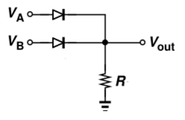 a) 0V b) -3V c) -5V d) -4V View AnswerAnswer: a Explanation: In an ideal diode model, the diode is considered as a perfect conductor in forward bias and perfect insulator in reverse bias. That is voltage drop at forward bias is zero and current through the diode at reverse bias is zero. Since both the diodes are in reverse bias mode, current through the diode is zero and we can consider the diode as an open circuit. So there is no voltage drop across resistor R.
9. I = 2mA, VB = 2V, and R = 2K are the values in the circuit shown below. View AnswerAnswer: a Explanation: In the ideal diode model, the diode is regarded as a perfect insulator in reverse bias and a perfect conductor in forward bias. In other words, there is no voltage drop at forward bias and no current flowing through the diode at reverse bias. Consider that diode is reverse biased. But, that does not satisfy KCL at the node. No incoming current is present. Hence diode is forward biased and short-circuited. Hence the output voltage = V = VB = 2V.
8. I = 2mA, VB = 2V, and R = 2K are the values in the circuit shown below. View AnswerAnswer: b Explanation: In the ideal diode model, the diode is considered to be a perfect conductor in forward bias and a perfect insulator in reverse bias. In other words, there is no voltage drop at forward bias and no current flowing through the diode at reverse bias. KCL cannot be properly applied at the node assuming forward bias for the diode. Hence diode is reverse biased. Since the diode is an open circuit, only the resistor R is conducting current. Hence voltage V = -2V.
3. When the ideal diode has V = 5V, VB = 2V, R1 = 2K, and R2 = 4K, find the current I. a) 0A and 1. 3mA b) 1. 231mA and 0. 33mA c) 3. 25mA and 0A d) 1. Explanation: In the ideal diode model, the diode is regarded as a perfect insulator in the reverse bias and a perfect conductor in the forward bias. In other words, there is no voltage drop at forward bias and no current flowing through the diode at reverse bias. The diode is forward biased and can be viewed as a short circuit when V=5V. Current through resistor R1 = V/2k = 2. 5mA. Current through resistor R2 = (V – VB)/4k = 0. 75mA. So total current is 3. 25mA. Since the diode is reverse biased at V = -5V, there is no current.
10. Vin = 3V, R1 = 6K, and R2 = 2K for the circuit shown below. The voltage V will be ________ a) 3V b) 0. 75V c) 1V d) 1. Explanation: In the ideal diode model, the diode is regarded as a perfect conductor in the forward bias and as a perfect insulator in the reverse bias. In other words, there is no voltage drop at forward bias and no current flowing through the diode at reverse bias. Due to the diode’s forward bias, R2 will experience the full voltage.
Que.2: List the ideal characteristics of an op-amp.
Infinite bandwidth Infinite CMRR (Common mode rejection ratio) Infinite slew rate Infinite input resistance Zero output resistance Zero output offset voltage Zero input offset voltage
FAQ
What is an analog circuit design?
Circuit stimulus is viewed as a continuously changing signal over time in analog design. With an emphasis on the fidelity/precision, consistency, and performance of the resulting waveforms, the circuit behavior is modeled in the time and frequency domains.
What is analog circuit with example?
Typically, analog circuits are intricate arrangements of op amps, resistors, caps, and other basic electronic parts. A class B analog audio amplifier such as this one is an example.
Is Analog Circuit design hard?
Most engineers will tell you that analog design is more difficult than digital design and that it necessitates more knowledge and consideration of more variables, including a profound understanding of effective power, precise measurement, wireless connectivity, and reliable circuit protection
Why analog circuits are needed?
But since analog signals make up the majority of signals in the real world, analog circuits are a crucial component of most electronic systems. In order for the physical world and electronic devices to communicate with one another, analog circuits are used to amplify, process, and filter analog signals before converting them to digital signals, or vice versa.