CAD digitally creates 2D and 3D design simulations of real-world objects to optimize the design before manufacturing.
Computer-aided design (CAD) is defined as the process of digitally creating design simulations of real-world goods and products in 2D or 3D, complete with scale, precision, and physics properties, to optimize and perfect the design – often in a collaborative manner – before manufacturing. This article explains how CAD works, its types, software, and use cases.
Computer aided drafting, commonly referred to as CAD has revolutionized the world of design and engineering. As a beginner you may have heard the term thrown around but remain unsure of what exactly CAD entails. Well, worry no more! In this comprehensive guide, I will walk you through everything you need to know about computer aided drafting.
When I first started out as a draftsman, CAD was still relatively new technology. Drafting by hand was the tried and true method that most professionals stuck to However, I could see the immense potential of CAD and jumped right in to learn this innovative technique Boy, am I glad I did! CAD has saved me countless hours and allowed me to take on more complex projects than I ever could by hand drafting.
If you’re considering learning CAD yourself you’ve made an excellent decision. CAD skills are highly valued across many industries like architecture engineering, and manufacturing. This guide will provide you with a strong foundation so you can hit the ground running. Let’s get started!
What is CAD?
CAD, or computer aided drafting, is the use of specialized computer software to create 2D and 3D models of physical objects and structures. It enables designers and engineers to create highly accurate drawings and plans.
With CAD, gone are the days of drafting painstakingly by hand using pencils, papers, parallel bars, and t-squares. CAD automates this process through smart tools and features that make drafting more efficient and accurate.
Some key capabilities of CAD software include:
- Creating 2D technical drawings and floor plans
- Building 3D models of parts and assemblies
- Adding dimensions, notes, and other annotations
- Managing design data and collaborating with team members
- Simulating how parts fit and operate together
CAD documents the entire design process, maintaining dynamic links between models, drawings, and annotations. This means that if an engineer makes a change to the 3D model, the corresponding 2D drawings update automatically. No more erasing and redrawing!
Brief History of CAD
Let’s step back in time and see how this game-changing technology came about. The origins of CAD date back to the 1960s when the first interactive graphics systems were developed by engineers like Patrick Hanratty and Ivan Sutherland.
These early CAD programs were quite primitive by today’s standards. But they laid the groundwork for the commercial CAD platforms we know today.
In the 1970s and 80s, CAD really took off as large companies started developing in-house software. The personal computer revolution in the 1990s made CAD accessible and affordable for small businesses.
Fast forward to today, CAD is an indispensable tool used across industrial sectors like automotive, aerospace, architecture, and manufacturing. Intuitive programs like AutoCAD, Solidworks, and Revit dominate the market with advanced capabilities.
Uses and Applications of CAD
CAD is applied in a diverse range of fields. Here are some of the most common applications:
Architecture and Construction
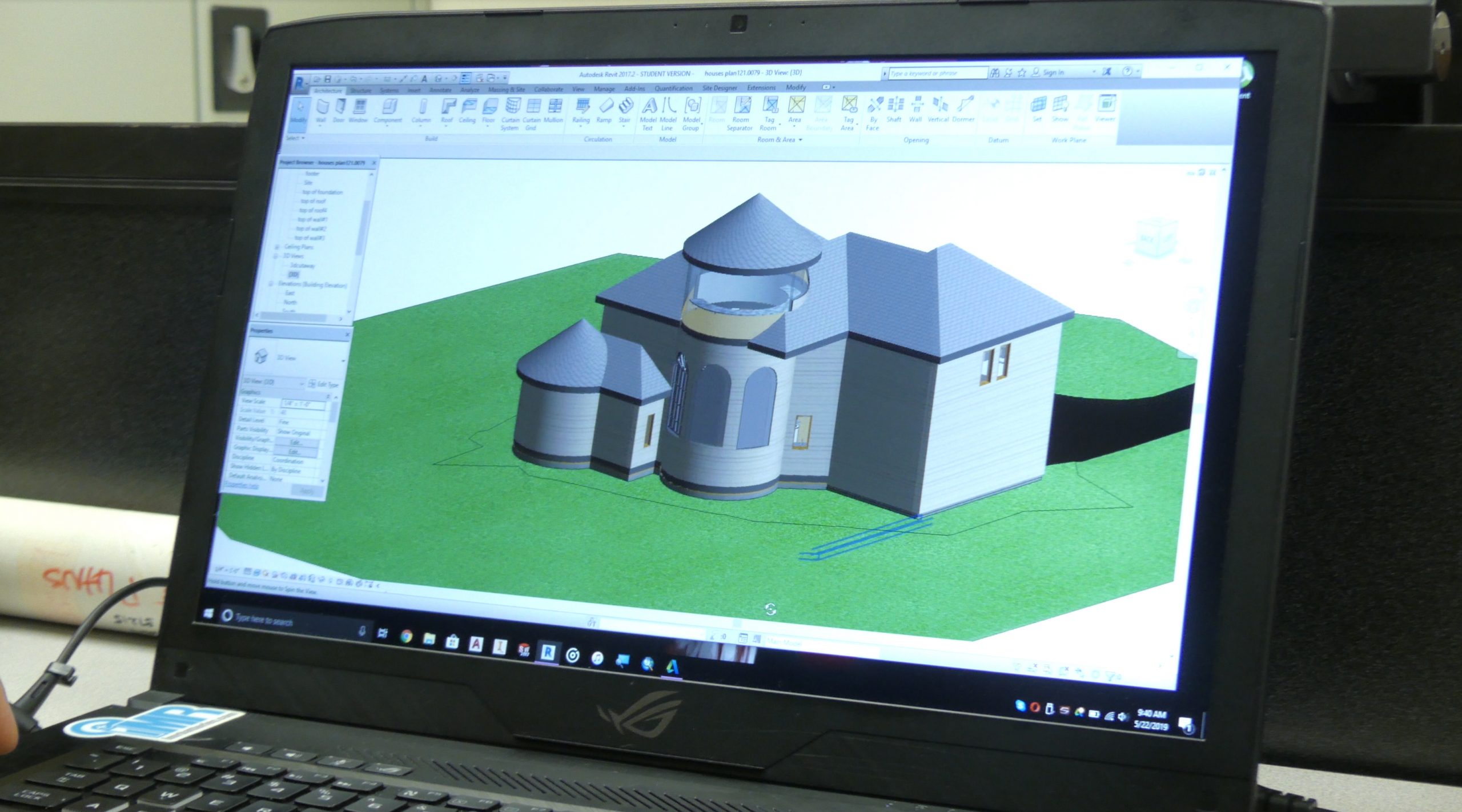
Architects use CAD software like Revit to create stunning 3D renderings and detailed construction plans. Builders can then reference these drawings to erect structures accurately. CAD allows architects to easily modify floorplans based on client needs.
Product Design and Manufacturing
CAD programs like Solidworks and AutoCAD are extensively used in product design and manufacturing. Designers create 3D CAD models of parts and send them to manufacturers. These models provide precise specifications for production. CAD data can also be used to program CNC machines.
Engineering
From electrical schematics to aircraft components, engineers across disciplines rely on CAD. It enables them to design, analyze, troubleshoot, and optimize complex systems before physically manufacturing them. Reducing errors in this planning stage results in huge cost savings.
Graphic Design
2D CAD software provides graphic designers with drafting tools to augment their creative work. Designers use these programs to create clean lines, shapes, and layouts for logos, posters, marketing collateral etc.
Clearly, CAD has far-reaching utility with game changing impacts across several industries. Next, let’s look at some tangible benefits of making CAD part of your design workflow.
Benefits of Learning CAD
Incorporating CAD into your skillset can enhance your career prospects and earnings potential. But it also simply makes you a more creative, productive, and precise designer. Here are some noteworthy advantages:
- Work faster by automating repetitive drafting tasks
- Create accurate designs rapidly by leveraging smart tools
- Easily visualize and understand complex 3D forms
- Modify or undo changes without having to redraw
- Quickly produce alternate design iterations
- Share CAD models with collaborators around the world
- Leverage CAD data to efficiently manufacture products
- Document entire design process for reference
- Simulate real world behavior early in design process
As you can see, CAD enables designers to swiftly bring their visions to life with less drudgery. Read on as we compare CAD with traditional manual drafting.
CAD vs Manual Drafting
To truly appreciate the power of CAD, it helps to compare it with old school pencil and paper drafting:
| Feature | Manual Drafting | CAD |
|---|---|---|
| Accuracy | Prone to human error | Precise down to decimal places |
| Speed | Slow and tedious | Rapid drafting and modifications |
| Visualization | Limited to 2D views | Realistic 3D models |
| Collaboration | Difficult to share hand drawings | Seamless sharing of CAD files |
| Documentation | Separate revisions for each draft | Entire history stored in one file |
| Simulation | Not possible | Test fit, motion, forces, etc. |
As this table illustrates, CAD offers huge advantages over manual techniques. The sophistication of CAD is lightyears ahead!
Now that we’ve covered the basics of CAD, let’s briefly discuss the steps involved in producing drawings using CAD software.
CAD Drawing Workflow
The typical stages in creating CAD models are:
1. Planning the Model
This involves determining the modeling approach, units of measurement, size, views required, level of detail etc. based on the end application.
2. Constructing the 2D/3D Geometry
CAD tools are used to draft lines, circles, arcs, splines, polygons and complex 3D surfaces. Dimensioning accurately is critical.
3. Adding Notes and Annotations
Notes contain text while annotations include things like symbols, arrows, and leaders. They convey additional design specifications.
4. Generating Drawings
2D part drawings, assembly drawings, and detailed drawings can be created from the CAD model.
5. Analyzing and Optimizing
The CAD model may be simulated to assess characteristics like aerodynamics, structural integrity, clash detection etc. Design tweaks can then be made to improve performance.
6. Final Output
The CAD data can be used to manufacture products or referenced during construction projects. Drawings can also be exported to common formats like PDF.
And that sums up a typical CAD drawing workflow. Of course, the exact steps vary across industries and applications. Next up, let’s discuss the different types of CAD software.
Types of CAD Software
There is a diverse array of CAD platforms available today catering to various specializations. CAD tools fall under the following broad categories:
2D CAD
As the name suggests, these programs are designed primarily for drafting in two dimensions. Some well known 2D CAD software are AutoCAD, DraftSight, ZWCAD, and FreeCAD. They allow users to create flat technical drawings.
3D CAD
3D CAD platforms enable modeling of objects in three-dimensional space. They generally provide advanced tools for solid modeling, surfacing, and rendering photorealistic images. Examples include SolidWorks, Creo, CATIA, and Inventor.
Specialized CAD
Certain CAD software are tailored for niche application areas. For instance, Revit for architecture, Civil 3D for civil engineering projects, and NX CAD for manufacturing.
BIM (Building Information Modeling)
BIM is a modern approach to construction design using intelligent 3D models. Revit is a popular BIM modeling tool.
Cloud-based CAD
These are CAD platforms accessed fully through the cloud. Cloud storage makes sharing and collaboration seamless. Onshape and Fusion 360 are leading cloud-based tools.
This brief overview just scratches the surface of the different flavors of feature-rich CAD software available today. Choosing the right one depends on your specific use case.
Now that we’ve covered the key aspects of CAD, let’s wrap up with some tips to kickstart your CAD learning journey.
Getting Started with CAD: Tips for Beginners
Here are some recommendations to help you start using CAD effectively:
-
Get appropriate hardware – A powerful PC with discrete graphics card ensures smooth CAD performance. An accompanying mouse with programmable buttons also boosts productivity.
-
Pick software suited for you – Assess your needs and budget when choosing between paid tools like AutoCAD or free ones like DraftSight.
-
Take advantage of built-in help – Most CAD programs have comprehensive documentation and tutorials to aid users. Make use of them.
-
Start with 2D fundamentals – Master sketching lines, rectangles, circles etc. before moving to advance
CAD using neutral file formats
These file types were developed to allow sharing between various software. As a result, interoperability is improved, which is essential. A neutral file format that any other software business may easily understand was required. Operating between several software packages is possible with CAD agnostic file formats. When you don’t want to spend money on additional CAD software, it’s pretty helpful.
They dismantle barriers and promote greater levels of collaboration. The most popular today are the CAD-neutral file types STEP, IGES, 3D PDF, JT, STL, ACIS, PARASOLID, and QIF file types. These CAD-neutral file formats do a great job of tearing down barriers, but not all of them are made equal.
How does computer-aided design work?
A standard CAD system requires the installation of a CAD software package and, occasionally, a graphics card on your computer to work. The graphics kernel is the brains of a CAD software application. The graphical user interface (GUI) is another crucial component of CAD software. The GUI is used to display the CAD geometry and collect user input.
Developing computer models with geometrical constraints is known as computer-aided design (CAD). These models often provide a three-dimensional representation of a component or a whole system on a computer screen. Developers can easily modify the model by altering the suitable parameters, which makes life easier for designers and engineers.
This indicates that the characteristics and relationships we feed into geometry, shape and size are controlled. If you use solid geometric modeling, which requires that you apply material first, the geometric will respond to forces similarly to real objects.
The mouse and keyboards are often used as input devices, and trackballs and digitizers are also occasionally utilized. The GUI transfers the input from the input devices to the graphics kernel in an appropriate format. The graphics kernel creates the geometric entities and instructs the graphics card to show them on the GUI.
Design engineers may plan and create their work on a computer screen with CAD, print it, and save it for upcoming revisions. The objects of traditional drafting are represented by CAD software for a mechanical design using either vector-based visuals or, in some cases, raster graphics that show the overall appearance of planned things. It involves more than simply forms, though.
According to application-specific norms, the CAD output must express information, such as materials, procedures, measurements, and tolerances, just like hand drafting of technical and engineering drawings. The software also considers the interactions between various materials and stakeholders, which is particularly important as more specifics are added to the drawings by subcontractors.
See More: Why the Future of Database Management Lies In Open Source
